Lab 1
- seanriddle9
- Sep 6, 2022
- 2 min read
Part 1
The first threadboard circuit we constructed was simple with only one LED and two batteries.

We then added a second LED in series with the first:


When we removed one battery, both LEDs turned off. Then we removed one of the LEDs, and the remaining LED turned back on.


Next we placed 3 LEDs in parallel with one battery:


Adding an extra battery to the parallel circuit seemed to make the LEDs a little brighter:

When we added a blue LED to the circuit, it did not turn on until the other 3 LEDs were removed:

Adding another LED in parallel with the blue LED turns the blue one off:
By switching the positions of the LEDs, we found that the LED that turned on was not the one closest to the battery, but likely the one using the least power.

Part 2
I decided to use 2 red LEDs for the breadboard circuits, which have "a typical forward voltage of 2.0V and a rated forward current of 20mA", according to the sparkfun store. Based on this, my calculations for which resistors to use are as follows:
For the series circuit:
R = (5V - 4V)/20mA = 50 ohms
For the parallel circuit:
R = (5V - 2V)/20mA = 150 ohms (2 resistors)
Part 3
Here are the photos of my series circuit.


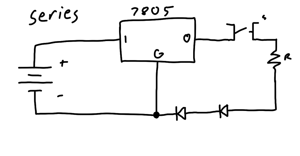
I didn't have much trouble building this one, between the provided diagram and the example circuit.
In this circuit, current flows from the 9V power source to the voltage regulator, which drops the voltage to 5V. The output of the regulator goes to a button switch, which allows current through only when pressed. Next, a 47 ohm resistor limits the current, which protects the LEDs from burning out. The current flows from the resistor into 2 red LEDs, which light up, and then goes to ground. In this circuit, the two LEDs are directly connected.
This was my first attempt at building the parallel circuit.


I didn't quite understand how to make the node split, so this circuit didn't work. I tried rearranging the wires:


This one ended up working.
This circuit is similar to the series circuit, but after the button, it splits into two wires that each lead to a 100 ohm resistor followed by an LED. Afterwards the paths reconnect to flow to ground. In this circuit, the two LEDs are kept in separate paths for the current to flow through.

Comments